Electronics & Electrical
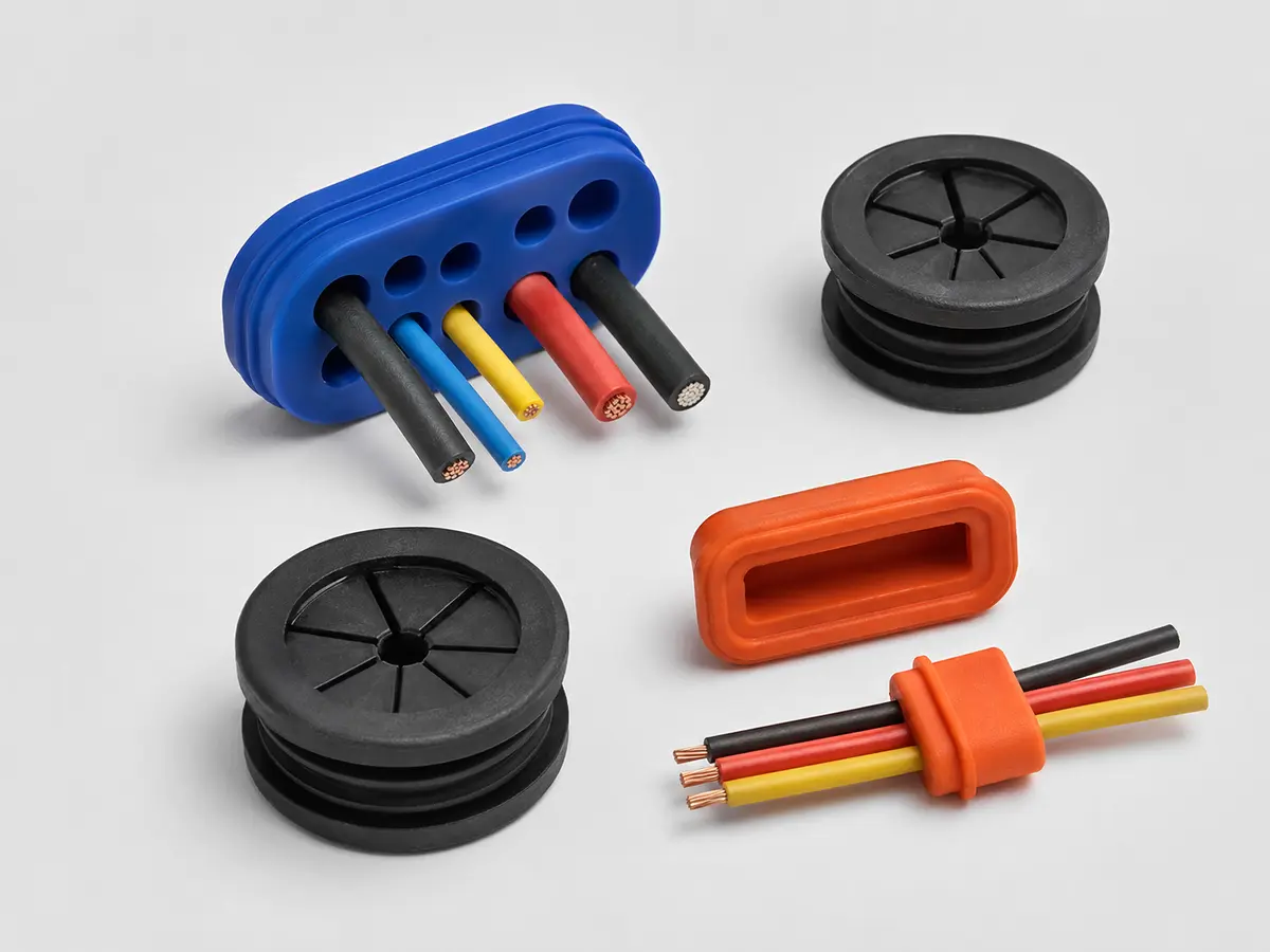
Waterproof Silicone Connector Seals and Wire Grommets
Custom connector interface seals, cable grommets and multi-hole wire seals for electronic assemblies.
View product details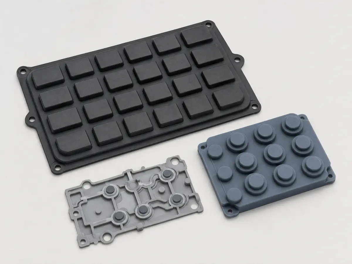
Drawing-based silicone keypads for control panels, instruments and sealed electronic interfaces.
Custom silicone keypads combine a flexible user interface with environmental protection and repeatable tactile behavior. The key geometry, web thickness, travel, force curve, legend method and contact structure should be developed together with the PCB and enclosure.
Custom Silicone Rubber Keypads for Electronic Controls is supplied as a custom B2B component for OEM, ODM and contract-manufacturing programs. It is not a fixed off-the-shelf retail item. Geometry, material, hardness, color, tolerances, inspection and packaging are developed from the customer drawing and the conditions in which the part will be assembled and used. MadeForSilicone reviews the available 2D/3D data before preparing a tooling and production quotation.
| Product | Custom Silicone Rubber Keypads for Electronic Controls |
|---|---|
| Material route | Solid silicone rubber; conductive carbon or contact structures by design |
| Molding process | Compression molding; optional printing, coating and assembly |
| Customization | Drawing-based dimensions, hardness, color, surface, functional features and inspection plan |
| Typical applications | Industrial controls, instruments, handheld electronics, access panels |
| MOQ | Project-based; evaluated from tooling, material, insert handling, inspection scope and order forecast |
| Supply format | Custom molded component, with secondary operation or subassembly evaluated when specified |
Electronic interfaces must be reviewed as an assembly rather than as an isolated rubber part. Our engineering review considers the enclosure, PCB or sensor position, cable path, mating plastic or metal, installation direction and the zones that must remain free of flash. Nominal dimensions alone are not enough: tolerance stack-up, compression after assembly, operator handling and access to ports or contacts can change the result. Early DFM feedback is used to identify practical parting lines, shutoff surfaces, draft, venting and inspection datums before tooling is released.
For this custom silicone rubber keypads for electronic controls program, the first review compares the functional intent with the information listed in the RFQ. The engineering team then confirms which features are critical, which surfaces are cosmetic, where measurement datums should be placed and how the part can be removed from the mold without damaging thin or retained features. Any recommendation is returned for customer approval before tool manufacture.
The preliminary material description is Solid silicone rubber; conductive carbon or contact structures by design, and the expected production route is Compression molding; optional printing, coating and assembly. These entries are a starting point, not a substitute for reviewing temperature, media, cleaning, movement, load, electrical or contact requirements. Exact grades and any special documentation are confirmed in the approved specification.
Material and molding route are selected after the working environment and order profile are understood. Solid silicone compression molding can suit many boots, keypads and sealing parts, while LSR injection molding can support fine features, repeatability and insert encapsulation. Secondary printing, coating, laser marking, trimming or assembly is evaluated only when required by the drawing. For parts that touch cables, sensors or housings, the insert fixture and allowable molding temperature are reviewed to reduce movement, contamination or damage during production.
The control plan focuses on the interfaces that affect electrical assembly and environmental protection. Typical checks include drawing dimensions at mating areas, surface and flash review, correct material and color, fit with approved mating samples, and project-defined sealing, tactile, pull or functional tests. Test conditions and acceptance limits must be agreed before samples are evaluated; results are not inferred from the material name alone.
For Custom Silicone Rubber Keypads for Electronic Controls, a practical control plan may cover the following items. Final limits, gauges, fixtures and sampling frequency are established from the customer drawing, approved samples and purchase requirements.
The usual project sequence is drawing review, technical clarification, quotation, DFM confirmation, tool manufacture, first-article sampling, customer evaluation and controlled mass production. When a physical sample is available, it can support the review, but a controlled drawing is still recommended for repeat orders. Tooling and unit pricing are prepared after material, cavity strategy, secondary operations, inspection scope and forecast volume are understood. Prototype and production timing therefore depend on the actual geometry and approval plan rather than on a generic catalogue lead time.
After sample feedback, agreed changes are recorded before the next trial or production release. Critical characteristics can be linked to an inspection report, mating fixture or functional test by project agreement. This approach gives purchasing, engineering and quality teams one common specification when the part moves from development to repeat production.
These components are commonly sourced by electronics OEMs, contract manufacturers, instrument builders and sensor companies that need a drawing-controlled silicone part integrated into an existing assembly. Typical uses for this product family include:
Please also state prototype quantity, first-order quantity and estimated annual demand. If a requirement is still under development, identify it as a target so it can be separated from a firm acceptance criterion. Drawings and models are handled as project information and are used to evaluate manufacturability, material, tooling and inspection needs.
Yes. Custom Silicone Rubber Keypads for Electronic Controls is developed from customer requirements. A 3D model plus a toleranced 2D drawing gives the clearest basis for tooling and inspection. A physical sample or mating component can help us understand fit and function, but dimensions, material and acceptance tests should be documented before repeat production.
The initial route is solid silicone rubber; conductive carbon or contact structures by design. Options can include single-key, multi-key and integrated sealing-mat layouts and custom hardness, color, surface texture and backlighting features. The final combination is selected after the operating environment, mating parts and validation method are reviewed; no material grade or compliance claim is assumed without a project specification.
Key factors include part size and complexity, mold cavities, undercuts or inserts, selected material, secondary operations, inspection fixtures, sample quantity and forecast volume. MOQ is therefore project-based. Send the RFQ information above, and we can prepare a manufacturing proposal and quotation for your engineering and purchasing review.
Custom connector interface seals, cable grommets and multi-hole wire seals for electronic assemblies.
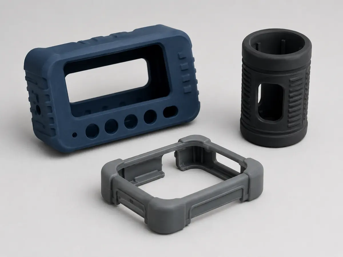
View product detailsFlexible molded covers for instruments, optical products, sensors and electronic subassemblies.
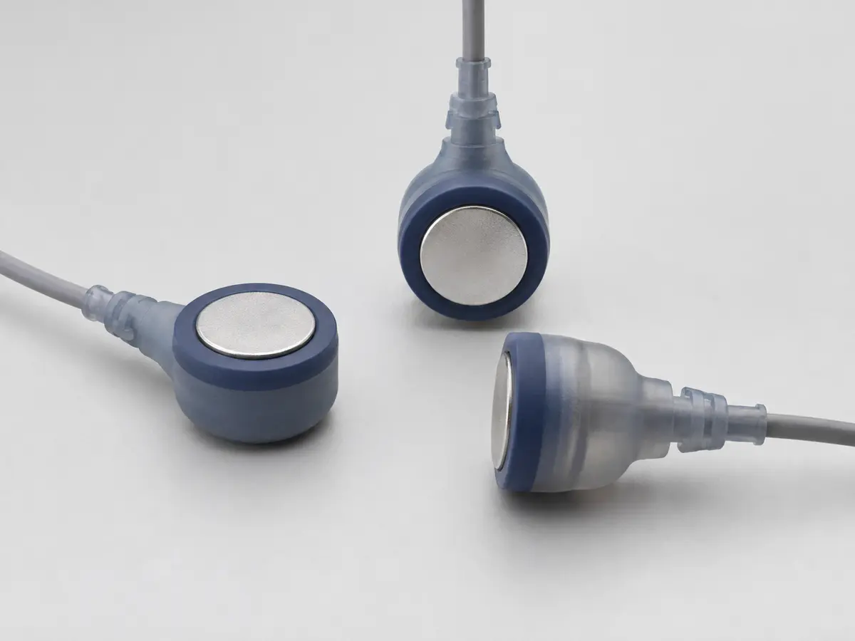
View product detailsLiquid silicone rubber encapsulation for selected sensor assemblies requiring environmental protection.
View product detailsSend the material, dimensions, application environment and estimated quantity. Our team will review the project and identify the next engineering step.