Industrial Custom Parts
Silicone Buffer Pads and Vibration-Damping Components
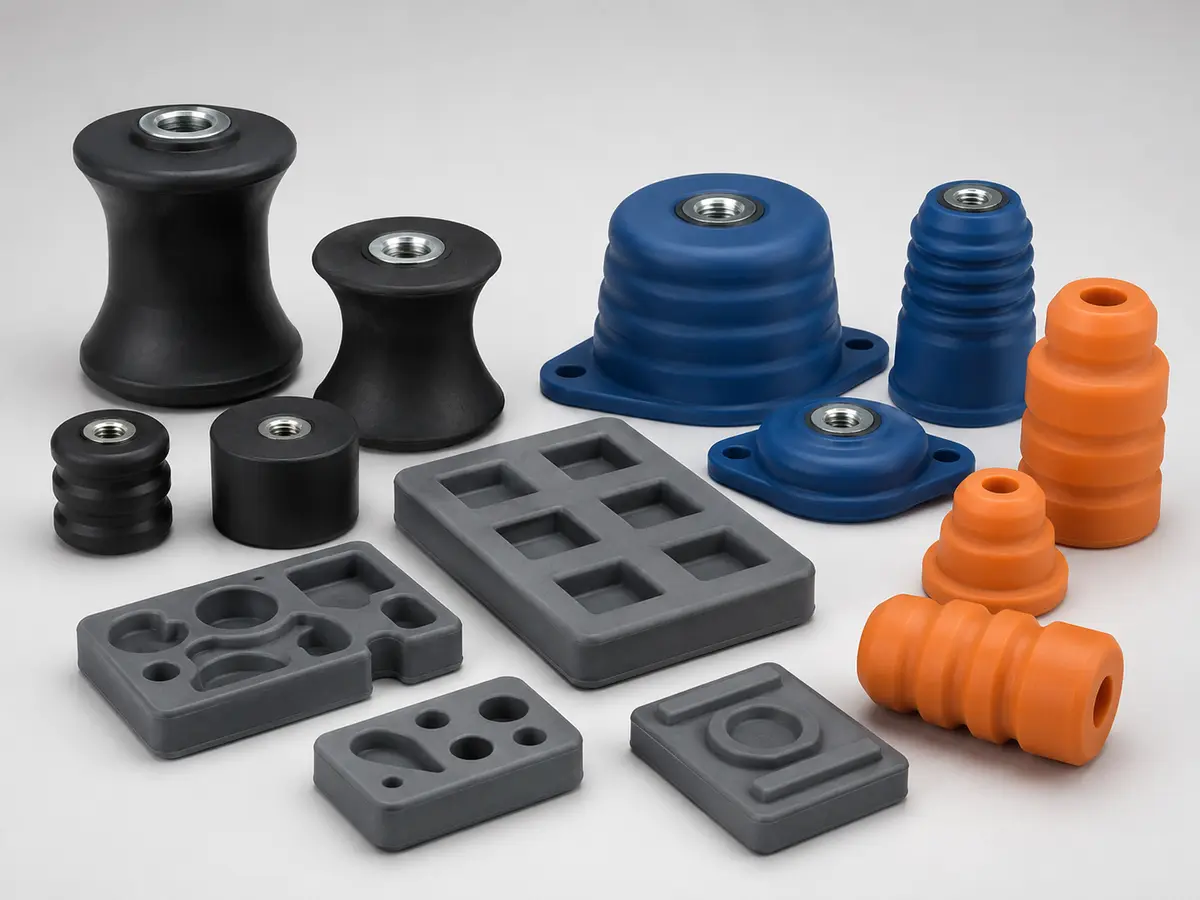
Custom bumpers, stops, feet and damping pads for machinery, instruments and precision equipment.
View product details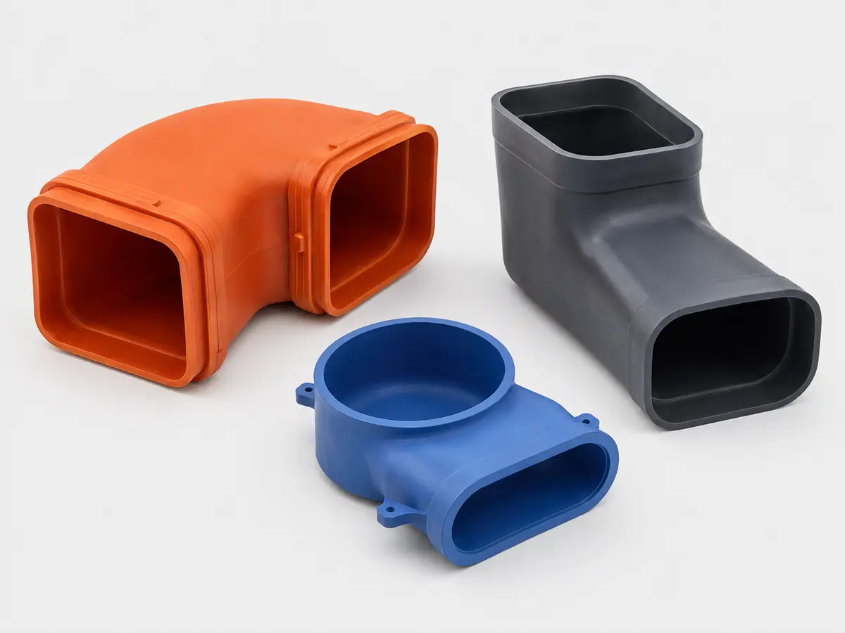
Flexible molded ducts, elbows and flow-guide components for compact industrial equipment assemblies.
Custom silicone air ducts and flow guides connect offset or moving interfaces where a rigid tube is difficult to assemble. The design should control internal area, bend collapse, wall thickness, end retention and the path needed to remove the molded part from its core.
Custom Silicone Air Duct and Flow Guide Components is supplied as a custom B2B component for OEM, ODM and contract-manufacturing programs. It is not a fixed off-the-shelf retail item. Geometry, material, hardness, color, tolerances, inspection and packaging are developed from the customer drawing and the conditions in which the part will be assembled and used. MadeForSilicone reviews the available 2D/3D data before preparing a tooling and production quotation.
| Product | Custom Silicone Air Duct and Flow Guide Components |
|---|---|
| Material route | Solid silicone rubber selected for airflow, temperature and flexibility |
| Molding process | Compression molding with project-specific core and demolding design |
| Customization | Drawing-based dimensions, hardness, color, surface, functional features and inspection plan |
| Typical applications | Cooling systems, instruments, equipment air paths, protective flexible connections |
| MOQ | Project-based; evaluated from tooling, material, insert handling, inspection scope and order forecast |
| Supply format | Custom molded component, with secondary operation or subassembly evaluated when specified |
Industrial custom silicone parts are developed around the function of the complete equipment assembly. The review covers loads, movement, available space, mounting method, airflow or protective path, required openings and the way the flexible part will be installed and serviced. Wall transitions, deep ribs, undercuts, closed sections and textured zones are checked for material flow and demolding. Where several functions are combined, each seal, cushion, membrane, duct or locating feature is assigned a priority so tooling compromises do not unintentionally affect the main performance requirement.
For this custom silicone air duct and flow guide components program, the first review compares the functional intent with the information listed in the RFQ. The engineering team then confirms which features are critical, which surfaces are cosmetic, where measurement datums should be placed and how the part can be removed from the mold without damaging thin or retained features. Any recommendation is returned for customer approval before tool manufacture.
The preliminary material description is Solid silicone rubber selected for airflow, temperature and flexibility, and the expected production route is Compression molding with project-specific core and demolding design. These entries are a starting point, not a substitute for reviewing temperature, media, cleaning, movement, load, electrical or contact requirements. Exact grades and any special documentation are confirmed in the approved specification.
Solid silicone compression molding, LSR injection molding or insert overmolding is selected after geometry, material, annual volume and secondary operations are reviewed. Tool construction must provide a practical parting line, venting, core removal and flash-control approach for the actual shape. Hardness, color and surface texture are project variables rather than fixed catalogue choices. Trimming, bonding, insert loading, marking or subassembly can be evaluated when the customer supplies measurable acceptance criteria.
The control plan is built from the product function and drawing datums. Dimensional checks focus on installation and mating features; visual criteria define flash, surface, color and permitted marks; and a fixture or functional test evaluates the real use condition. Depending on the part, this may include deflection under load, airflow fit, retention, movement, impact cushioning or assembly checks. Inspection methods for soft parts are agreed to avoid distortion from uncontrolled measuring force.
For Custom Silicone Air Duct and Flow Guide Components, a practical control plan may cover the following items. Final limits, gauges, fixtures and sampling frequency are established from the customer drawing, approved samples and purchase requirements.
The usual project sequence is drawing review, technical clarification, quotation, DFM confirmation, tool manufacture, first-article sampling, customer evaluation and controlled mass production. When a physical sample is available, it can support the review, but a controlled drawing is still recommended for repeat orders. Tooling and unit pricing are prepared after material, cavity strategy, secondary operations, inspection scope and forecast volume are understood. Prototype and production timing therefore depend on the actual geometry and approval plan rather than on a generic catalogue lead time.
After sample feedback, agreed changes are recorded before the next trial or production release. Critical characteristics can be linked to an inspection report, mating fixture or functional test by project agreement. This approach gives purchasing, engineering and quality teams one common specification when the part moves from development to repeat production.
These made-to-drawing components serve equipment builders, optical and instrument manufacturers, automation projects and specialty OEM/ODM assemblies that require non-standard silicone geometry. Typical uses for this product family include:
Please also state prototype quantity, first-order quantity and estimated annual demand. If a requirement is still under development, identify it as a target so it can be separated from a firm acceptance criterion. Drawings and models are handled as project information and are used to evaluate manufacturability, material, tooling and inspection needs.
Yes. Custom Silicone Air Duct and Flow Guide Components is developed from customer requirements. A 3D model plus a toleranced 2D drawing gives the clearest basis for tooling and inspection. A physical sample or mating component can help us understand fit and function, but dimensions, material and acceptance tests should be documented before repeat production.
The initial route is solid silicone rubber selected for airflow, temperature and flexibility. Options can include straight, elbow, reducer and irregular flow paths and clamping beads, flanges and locating tabs. The final combination is selected after the operating environment, mating parts and validation method are reviewed; no material grade or compliance claim is assumed without a project specification.
Key factors include part size and complexity, mold cavities, undercuts or inserts, selected material, secondary operations, inspection fixtures, sample quantity and forecast volume. MOQ is therefore project-based. Send the RFQ information above, and we can prepare a manufacturing proposal and quotation for your engineering and purchasing review.
Custom bumpers, stops, feet and damping pads for machinery, instruments and precision equipment.
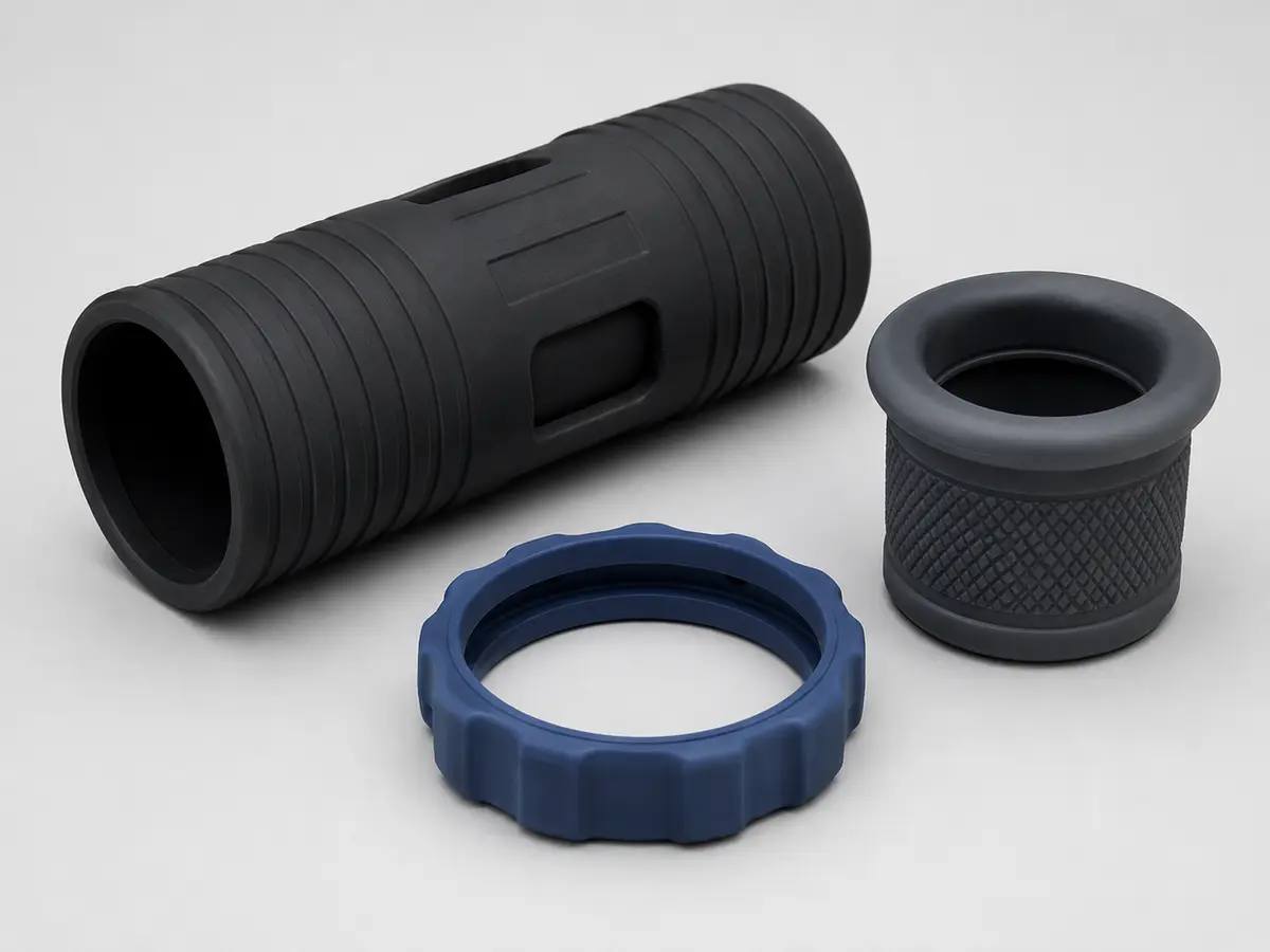
View product detailsMolded protective sleeves and covers for binoculars, telescope components, sensors and optical instruments.
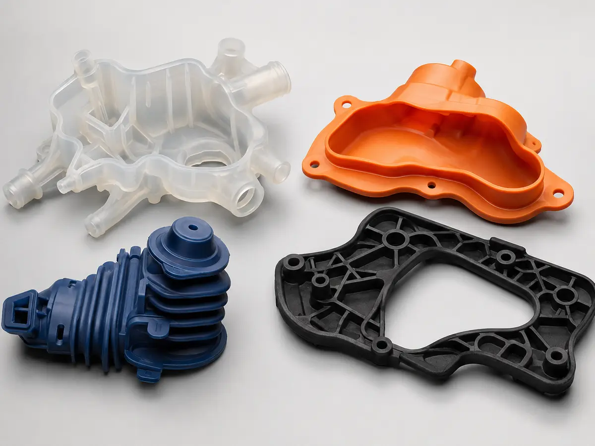
View product detailsIrregular, multi-feature molded silicone parts developed from drawings, samples or assembly requirements.
View product detailsSend the material, dimensions, application environment and estimated quantity. Our team will review the project and identify the next engineering step.